• We have updated the site to the latest version. You will be required to log in to make sure your account is active. There are quite a few new functions so it will take a little time to get use to it. Please post if you see or have any issues.

Wont start without unplugging capacitor

You have to concentrate on #6 on that list and fix the 6 volts, the capactior needs 12v from the sled in order to charge correctly. Reverse wont work without the capacitor since thats what holds the charge to keep everything alive while the motor is powering down.
Also the drain of the capacitor itself sounds fast, its possible its bad.

I have 2 caps did the same thing. but you can be right, i have one on ordered just in case

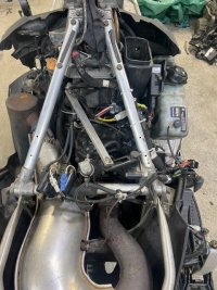
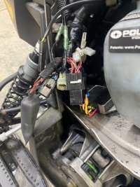
First, thank you for replying, as you know the cap is tight in to the VR (
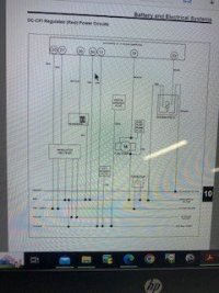
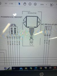
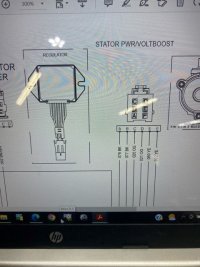
Combination AC/DC Regulator - Battery
Charge Rectifier) . see attached file which mean that only a few parts can drown it...
1, EV Solenoid. I did unplugs , same thing 6 volts dc out
2. The fuel pump, took it off same thing
3. the relay, take off the relay , and I have a new one, same thing
4. that brown wire Chassis ground, we are grounded

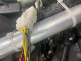
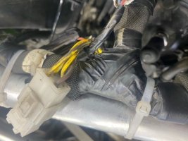
the only thing IC is the red wire is tight in the the orange wire (external power)....hmmm I did not really check into that....but i will

If you think of anyting I miss, let me know


Again, I thank you very much for helping in the matter and hope it will help others

Pro
 

Attachments

  • poalhhhhhhhhhhhhhhhh.jpg
    poalhhhhhhhhhhhhhhhh.jpg
    21 KB · Views: 82
That pic you posted looks like the pro-ride chassis manual, thats not right for your sled if its a 2016, you need the AXYS chassis manual (2015+) since there are alot of changes to the wiring in the newer chassis.
Just noticed in your first post you only mention 1 relay, all the AXYS sleds have at least 4 relays, 5 if its electric start. There are 2 next to the pipe and the 3rd is in the wire bag in front of the oil bottle, 4&5 are right above the battery. One of those is a load shed relay that controls the chassis voltage, I would start by hunting these all down and replacing them ALL. Be sure to use higher quality aftermarket ones as the factory ones are chinese junk.
 
850Switchback has a good suggestion. the crimps on the stator that went bad on me were down where the main colored wires met the coils windings. If you had already put a new stator on it, I would doubt that would be the issue that your dealing with. when I tested my capacitor it would hold its full charge for 5 minutes before it drops a single volt.
 
That pic you posted looks like the pro-ride chassis manual, thats not right for your sled if its a 2016, you need the AXYS chassis manual (2015+) since there are alot of changes to the wiring in the newer chassis.
Just noticed in your first post you only mention 1 relay, all the AXYS sleds have at least 4 relays, 5 if its electric start. There are 2 next to the pipe and the 3rd is in the wire bag in front of the oil bottle, 4&5 are right above the battery. One of those is a load shed relay that controls the chassis voltage, I would start by hunting these all down and replacing them ALL. Be sure to use higher quality aftermarket ones as the factory ones are chinese junk.
Yes you are right, I downloaded the 2015-17 AXYS, and Im more confused now then ever. hear why. First I ran the vin number to make sure I had a 2016. and yes it is.

If you notice the wires going into the VR from the sled (3rd picture), you will notice that the two yellows are on top, the orange in the middle (which and connected to the yellows) and with have the Brown and red at the bottom. like the schematic on the right (2013 schematic). if you look at the 2nd picture (2016 schematic) , you will notice that is doesn't Match my wiring on the sled, I also do not see any other relays.
 

Attachments

  • 2016 Polaris 600 rmk c.jpg
    2016 Polaris 600 rmk c.jpg
    63.2 KB · Views: 82
  • 2016 Polaris 600 rmk d.jpg
    2016 Polaris 600 rmk d.jpg
    59.9 KB · Views: 82
  • 2016 Polaris 600 rmk b.jpg
    2016 Polaris 600 rmk b.jpg
    61.8 KB · Views: 82
  • 2016 Polaris 600 rmk A.jpg
    2016 Polaris 600 rmk A.jpg
    90.5 KB · Views: 81
  • 2016 Polaris 600 rmk e.jpg
    2016 Polaris 600 rmk e.jpg
    56.5 KB · Views: 87
  • 2016 Polaris 600 rmk f.jpg
    2016 Polaris 600 rmk f.jpg
    78.6 KB · Views: 83
850Switchback has a good suggestion. the crimps on the stator that went bad on me were down where the main colored wires met the coils windings. If you had already put a new stator on it, I would doubt that would be the issue that your dealing with. when I tested my capacitor it would hold its full charge for 5 minutes before it drops a single volt.
both of mine caps that I have (borrow another one from a blown sled with are rebuilding the motor) do not hold charge at all they drop right away after I take off DC voltage in within 1.5 minutes I have 1.6 volts.
 
Ok I was wrong, this is where Polaris makes it confusing. That particular 144 RMK sled is still the old pro-ride chassis, so the first manual was the correct one. Does the service manual version you have cover up to the '16 models? The version I have stops at '13 and not sure if they made any changes after that.
Have you checked the main ground connection to the chassis? There should be a group of brown wires bolted to the frame, its usually right near the left front suspension.
Also check the voltage at the plug labelled "DC power" above the clutch
 
Last edited:
Ok I was wrong, this is where Polaris makes it confusing. That particular 144 RMK sled is still the old pro-ride chassis, so the first manual was the correct one. Does the service manual version you have cover up to the '16 models? The version I have stops at '13 and not sure if they made any changes after that.
Have you checked the main ground connection to the chassis? There should be a group of brown wires bolted to the frame, its usually right near the left front suspension.
Also check the voltage at the plug labelled "DC power" above the clutch
Hello, sorry a little late, was at camp. The manual goes to 2017. I have 2 ground on the left above the front shock and another ground on the right below the starter on the frame. Voltage coming out DC out is 6 vdc same as Cap. She will start with no caps still and run pretty good. Would you happen to know what should I get at the stator the two yellow, I get 12.5vdc.

Thank you for your help
 
Not sure directly off the stator, its still AC at that point but they don't give a value for it, just the ohms for the circuit. The voltage regulator converts it to DC.
How is the tail light, is it bright or very dim? The instrument cluster works ok?
Have you checked all the pins in the connectors from the stator to that regulator to make sure they are solidly connected to the plastic connectors and making good contact? You are going to probably have to start searching for a worn thru wire somewhere that is touching the chassis.
I saw that too, doesn't say, only the ohms and output to the red wire off the VR (14.6vdc), What I did today is took the grounds off a cleaned them good. Also did process of elimination and didn't help, so what I also did is unplug the red wire from the whole system and still get 6vdc off of it without been plugged into the harness. I did check to make sure all my ground was good and not open. I also made sure that the ECM was grounded also. All my lights work and Dash also. no flickering. I'm running out of idea. I have a cap coming in but i don't think it will fix my problem of 6vdc. I also checking for wires rubbing on metal, but as of now nothing.

Thank you
 
I did a little looking around, to get the 14V DC output from the regulator on the red wire you should be seeing more than 20V AC input from the stator on those yellow wires for the conversion to happen. I would be scrutinizing all the connections & wiring from the stator to the VR.
You are right, the capacitor isn't going to do anything without 12v+ DC on that red wire regulated DC circuit.
Ya I did check connections specially the yellow to VR, but maybe the other wires from the stator are drowning my yellow power, I may like to disconnect and check again the yellow output to VR after disconnecting everything, we did try a new stator and flywheel, same result.

Thak you again for your help
 
I'm not sure that will do anything, the three X,Y, & Z circuits they show in the diagrams are wired independently of each other.
What is the AC voltage you get when you probe across the yellow wires going ot the regulator?
 
I'm not sure that will do anything, the three X,Y, & Z circuits they show in the diagrams are wired independently of each other.
What is the AC voltage you get when you probe across the yellow wires going ot the regulator?
they are yes, all individual wingdings. the most I got was 12VAC (Yellows Z) which give me 6VDC out of VR(RED)
 
Are you getting 12v on each yellow probing to ground individually or did you put the meter probes on both yellows simultaneously?
 
Last edited:
Are you getting 12v on each yellow probing to ground individually or did you put the meter probes on both yellows simultaneously?
Meter on both (yellows)Z wires, on AC Setting and with a Regulator Adaptor Setting at DC. getting same result
 
I'm honestly out of ideas, only thing I have left, did you check the yellow wires for continuity to ground? directly at the stator plug and at the connection to the VR?
 
I'm honestly out of ideas, only thing I have left, did you check the yellow wires for continuity to ground? directly at the stator plug and at the connection to the VR?
I think I did but when I get back home if the sled is there i definitely recheck to see if the stator yellow wire is grounded. I also noted.
that the ohms resistance from the VR output red to brown (ground) is around 560 ohms plugged in and unplugged goes up to 700 ohms. FYI . seems high,

Thank You
 
I'm honestly out of ideas, only thing I have left, did you check the yellow wires for continuity to ground? directly at the stator plug and at the connection to the VR?
open circuit on the yellows (Z) and brown and yellow (Y) to ground
From Stator directly and to the VR Plugged or unplugged
unplugged connector to stator and this is the result below
Yellows .4 to .5 ohms and 5.8VAC when turn key
Yellow/Brown or Black/black in my case from stator .3 Ohms and 7.9Vac when turning key

I notice the following at the connector from stator to VR
the two top yellows (1st pix) go into brown and yellow (books says it should go to yellows)
the two black bottom(2nd pix) go into the two yellows going to the VR (books says should go to the Brown and yellow)
Is this wrong or can the winding on Y and Z are the same and can be interchange ???
Doesn't look like in was played with
Tempted to switch them
 

Attachments

  • 600 polaris stator connector b.jpg
    600 polaris stator connector b.jpg
    57.2 KB · Views: 78
  • 600 polaris stator connector a.jpg
    600 polaris stator connector a.jpg
    68.5 KB · Views: 74
Check the resistance of both those stator circuits, per the manual the Z circuit to the VR has the higher resistance value 0.2 Ohms ( more coils).

They unfortunately didn't give a good way to check the VR itself, the AXYS manual has diode checks you can perform on that VR but I havent seen it anywhere for the pro ride VR's .
Ya if you check above the reply, i did and its is a Little higher, i did switch the wire around as per the schematic, to my surprise it did start with cap and I had reverse, i shut it down try it again twice and worked, I then wrap the wires with cloth. put her back together and when to test her out outside. Didn't want to start again, same problem. needed to take the cap off to start and no rev. WTF, I put the meter on cap while running and I got 8vdc off the cap. raddle the wire and same. I don't know anymore


Back
Top Bottom